 It is a fundamental principle that all piping systems require support and some degree of flexibility. Today’s pipe stress engineer must go beyond checking for just allowable pipe stresses, and check for load limitations on key equipment and/or support structure. This requires not just understanding general piping codes such as ASME B31.1 & 31.3, but also careful consideration of codes that address nozzle loading such as API 610 5.5.1 and ANSI/HI 9.6.2. Additionally, essential equipment suppliers have voiced their concerns relating to the damaging effects of high nozzle loading on their equipment. Unfortunately, this concern is often, and incorrectly, associated with rubber expansion joints based on an unacceptable pressure thrust force they could impose. Some equipment suppliers have even taken an extreme approach and recom-mended pipe stress engineers eliminate expansion joints, increase the rigidity of the piping system and tighten installation tolerances.
This approach is both impractical and problematic because it does not adequately take into consideration the fundamentals of thermal growth and contraction of the piping system, ground settlement, vibration, realistic piping misalignment and other common external forces and displacements imposed on the piping system. This approach also hinders the efforts of owners and pipe stress engineers who desire piping systems with a smaller footprint, lower construction cost, improved energy efficiency, modular construction and less support structure. Systems designed without rubber expansion joints also lack the common benefits of absorbing all directional movements including ground settlement, reducing noise and vibration, having a cycle life in the tens of millions, compensating for typical misalignments of 0.185”, providing access to piping and equipment, and having superior corrosion and abrasion resistance. An optimal approach requires understanding the imposing pressure thrust forces from some expansion joint arrangements, and when needed, incorporating more advanced rubber expansion joint arrangements that can facilitate both system flexibility and restraint.
More advanced rubber expansion joint arrangements should not be confused with simply adding control rods to an unrestrained rubber expansion joint (Illustration 1). This is because setting control rods with gaps still imposes 100% of the pressure thrust force on the system and setting them without gaps will lack axial flexibility. This no-gap setting is effective in restraining the full pressure thrust force and obtaining all common rubber expansion joint benefits excluding axial flexibility.
Looking at the Alternatives
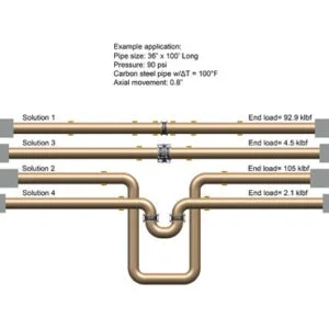
As a helpful exercise, the pipe stress engineer may look at several alternative solutions for the same application and compare the different end load results. Alternative solutions can include incorporating rigid pipe loops, traditional unrestrained rubber expansion joints, and/or more advanced rubber expansion joint arrangements. Illustration 2 shows four solutions to an example application of a 36” diameter carbon steel pipe with a 100’ axial run under 90 psi with temperature fluctuation of 100°F. Each solution will restrain the pressure thrust forces, absorb the axial thermal movement of 0.8” and keep the piping system within allowable stresses. However, each solution will have very different end loads. For simplicity, load factors common to all solutions, such as pipe and fluid weight, are ignored, as well as the fact that actual pipe stress engineers will likely utilise FEA software including AutoPIPE or CAESAR II.
SOLUTION 1 incorporates an unrestrained expansion joint installed between two main anchors with numerous guides at specific spacing. This is a good solution when there are no load limitations on the equipment and/or support structure. The common benefits of incorporating rubber expansion joints are also obtained. The consequence of an unrestrained expansion joint being installed axially in-line is the pipe no longer being able to carry the pressure thrust force in tension, and so the pressure thrust force must now be transmitted as a compressive load onto the systems ends, thus requiring main anchors. The end load can be calculated as the sum of the pressure thrust force, the spring rate load of the rubber expansion joint and some minor friction loads from the pipe guides. The end load for Solution 1 extends to be approximately 92,900 lbf (pounds force). This illustrates why many equipment manufacturers would not want their equipment to be treated as a main anchor and forced to carry such a heavy load.
SOLUTION 2 incorporates a rigid piping loop installed between two intermediate anchors with a limited number of guides. This is a good solution when there are no space restrictions or a need to reduce material or energy costs, and there is no need for the common benefits gained from incorporating rubber expansion joints. The carbon steel pipe will carry the full pressure thrust force in tension and does not transfer that load on to the system’s ends. The end load can be calculated as the sum of the load deflection values from the solid pipe loop using the Kellogg method and some minor friction loads from the pipe guides. The end load for Solution 2 extends to approximately 105,000 lbf, a force greater than that of the pressure thrust force in the example application. Equipment manufacturers should be just as concerned with this heavy load as they are with eliminating pressure thrust forces.
SOLUTION 3 incorporates an in-line pressure balanced rubber expansion joint installed between two intermediate anchors with a limited number of guides. This is the only effective solution for directly absorbing large axial thermal movements while continually self-restraining the pressure thrust forces. This advanced rubber expansion joint arrangement consists of tie devices interconnecting its main joint section to its opposing balancing joint section (Illustration 3). This is an optimal solution when there are load limitations on the equipment and/or support structure and there is a high value placed on reducing the system footprint, as well as saving material and energy costs. The common benefits of incorporating rubber expansion joints are also obtained. The end loads can be calculated as the sum of the spring rate load of the expansion joint and some minor friction loads from the pipe guides. The end load for Solution 3 extends to approx-imately 4,500 lbf; a very manageable load.
SOLUTION 4 incorporates a flexible pipe loop installed between two intermediate anchors with a limited number of guides. This advanced rubber expansion joint arrangement consists of two universal tied joints for maximum lateral movement capability, inter-connected in a compact pipe loop (Illustration 4). This is a very effective way to absorb large axial thermal movements from the longer adjacent pipe runs. It is also an optimum solution when there are load limitations on the equipment and/or support structure and there is some value placed on reducing the system footprint, as well as saving material and energy costs. The common benefits of incorporating rubber expansion joints are also obtained. The end load can be calculated as the sum of the lateral spring rate loads of the two expansion joints and some minor friction loads from the pipe guides. The end load for Solution 4 extends to approximately 2,200 lbf; an extremely low and very manageable load.
An Optimal Solution
When concerned about the load carrying capabilities of any essential equipment and/or support structures, an optimal solution is neither to increase rigidity into the piping system or ignore the imposing pressure thrust forces as an effect of some expansion joint arrangements; but rather to incorporate more advanced rubber expansion joint arrangements that can facilitate both system flexibility and restraint when needed. This approach is also very much in line with owners and stress engineers who desire piping systems with smaller footprints, lower construction costs, improved energy efficiency, modular construction and less structural support.
—
Author Lloyd B Aanonsen, P.E. is President of General Rubber Corporation and has been directly involved in the design and manufacture of performance rubber expansion joints for over 30 years. He has authored numerous articles on the subject and is an active member of the Fluid Sealing Association and the Hydraulic Institute.