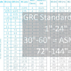
Flange Data

Please review the FSA APPENDIX B: Common Flange Dimensions/Drilling Chart via the following link for standard available drilling patterns for expansion joints, rubber pipe, retaining rings and control units. For custom drilling or flange data not shown, please contact us.
FSA APPENDIX B: Common Flange Dimensions/Drilling Chart
Notice: Most manufacturers can furnish products meeting the following drilling/flange standards, among others:
– British Standard 10:1962
– EGMA, Tables 2-3-5-5/1962
– ISO, International Std. 2084
– ISO, International Std. 2536
– NBS Product Standard PS 15-69
– API Standard 605
– DIN-ND 2501 Tbls 6-10-16
– SMS 2033
– DIN 2633
– RSF 1583
– NF.E 29-201 PN 6-10-16
Notes:
1) When ordering/specifying expansion joints, rubber pipe, retaining rings, or control unit assemblies, always note the mating flange drilling specification or the actual dimensions if specification is unknown. In the absense of this data, these products will be drilled to ANSI B16.1 Class 125, or to the individual manufacturer’s printed drilling specification.
2) When products are manufactured to ASTM F1123-87. They should be drilled to MIL-F-20042C or ANSI B16.5 Class 150, as specified by the customer.
3) AWS = American War Standard / ASA = American Standards Association, changed to USAS / USAS = United States of America Standards Institute, changed to ANSI / ANSI = American National Standards Institute / AWWA = American Water Works Association / API = American Petroleum Institute
4) Drilling is available but not shown for the following: 1914-78″, 90″; AWWA C207-78-114″, 126″, 138″.
