 Warning
Rubber Expansion Joints (REJ) may operate in pipelines or with equipment carrying fluids and/or gases at elevated temperatures and pressures, and may transport hazardous materials. Precautions should be taken to protect personnel in the event of leakage or spray. REJs should only be installed where inspections are possible and should be installed over areas with proper drainage. REJ installations should be conducted by authorized and qualified pipe fitters. If the REJ is to be installed underground, or will be submerged in water, contact General Rubber Corporation (GRC) for specific recommendations.
Service Conditions & Inspection
Check that the temperature, pressure, vacuum and movement ratings for the REJ are not exceeded by system conditions. Also verify that the REJ elastomers are compatible with the process fluid or gas. If any of these ratings are exceeded, contact GRC immediately. Visually inspect REJs for cuts and gouges from transport or worksite handling prior to installation. Be advised that hand-wrapped REJs are built using “cure tape” which may leave impressions, folds or creases in the cover; these are typical of the REJ industry and are only cosmetic in nature. There may also be residual Talc on the inside of the REJ — a typical mold release which is nontoxic and harmless — this chalk-like surface finish is also cosmetic in nature and common of the REJ industry.
Alignment
REJs should not be used to rectify piping misalignment of more than 1/8” [3.2mm]. Exceeding allowable misalignment value may cause damage and void the warranty. Misalignment will also detract from rated movements. The use of pipe guides may be required to maintain proper alignment and support the weight of the pipe. Consult GRC’s Technical Guidelines for specific recommendations. Note: GRC can fabricate REJs with built-in offsets to accommodate field dimension variances.
Anchoring
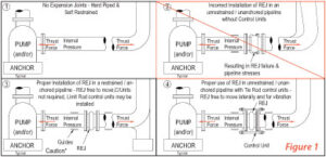
When using REJs in a piping system, they must be restrained from pipeline pressure thrust forces. The magnitude of this force is the pressure times the projected cross-sectional area in the pipeline and is imposed on any change of direction or termination point. If these forces are not properly restrained, they will over-extend the REJ and cause failure. They may also subject the pipeline and its components to unanticipated stresses. The pipeline should have restraints/anchors at any change of direction or termination point. The illustrations of pipeline restraint/anchoring shown in Figure 1 are to provide better understanding of the impact of pressure thrust forces only. These illustrations also provide better understanding of the role of control units in a typical piping system. It is not recommended to install more than one single REJ between two adjacent anchors in any straight pipe run. The Caution note on Illustration 3 (see Figure 1) is to clarify that a pump or other sensitive equipment should not be used as an anchor unless the applied pressure thrust forces are within allowable nozzle loads as dictated by the equipment manufacturer. Contact GRC with any questions or concerns prior to installation.
Control Units
In a restrained/anchored pipeline, it is recommended to use a Limit-Rod Control Unit configuration to restrict the REJ’s movement to within its allowable axial, lateral, and angular movements. The Limit Rod Nuts must be set with proper spacing/gaps to allow freedom of movement during normal operation (see Figure 2). In the event of a main anchor failure, they are designed to prevent the REJ’s overextension by restraining the full pressure thrust force after the space/gap is consumed. • In an unrestrained/unanchored pipeline, it is recommended to use a Tie-Rod Control Unit configuration to continuously restrain the full pressure thrust force while permitting lateral deflection (see Figure 2). The Tie-Rod Control Unit can be snug tight after installation of flange bolts and after accommodating for minor misalignment. Additionally, angular rotation can be accommodated with a two Tie-Rod configuration located 90° opposed to the direction of rotation. • There are many Control Unit configurations; Figure 2 illustrates the most common. Contact GRC for further clarification if the illustration does not match what is being installed.
Mating Flanges
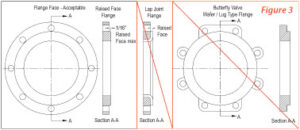
Install the REJ against the mating flange. It is recommended to install bolt heads against the retaining ring side. The use of SAE-sized washers at the retaining ring split is also recommended, otherwise take precaution to ensure that the bolt threads do not come in contact with the REJ arch section. Face-to-face dimensions (F/F) of the REJ as shown on a typical submittal drawing should be within 1/8” [3.2mm] of the breech opening. Make sure the mating flanges are clean and are either the flat-face type or have no more than 1/16” [1.5 mm] of a raised face. Never install a REJ next to a wafer type check valve, butterfly valve, lap joint flange, Victaulic, or any other non-continuous flange, as it will cause flange damage and void the warranty. An acceptable mating surface can be achieved with the use of flange spacers or filler flanges. Non metallic flanges and some demanding applications may require a machined surface for proper sealing as per AWWA C207 Section 4.2.2. Contact GRC for help with any questions or concerns.
Bolting Torque
Tighten bolts in stages by alternating around the flange in a star pattern. If the REJ has an integral rubber flange, the bolts should be tight enough to make the outer rubber flange bulge slightly between the retaining ring and the mating flange. Avoid using any rubber gaskets. Contact GRC for recommended torque values based on your operating pressures. REJ flanges may have to be retightened after initial installation due to the rubber flanges relaxing and taking a compression set. Check bolt tightness two or three weeks after installation and retighten as needed. Never retighten bolts when the pipeline is under pressure.
Cost-Effective Solution
An optimal design does not necessarily mean higher pressure or temperature ratings, because these features typically increase the product’s stiffness and cost. With a proven track record that dates back to 1950, General Rubber has the experience and is confident that we can develop an optimal and cost effective solution to meet your requirements. Our abrasion and corrosion-resistant materials can be superior to even the most exotic metals. Our large inventories and modern U.S. ISO 9001 & 14001 certified manufacturing facility also mean quick deliveries, as well as top quality products and services.
Maintenance
REJs should be inspected regularly to insure they are in proper working order. Check the face-to-face dimension for any changes and make sure it is still within allowable limits. Look for any obvious bulges, tears, cracks or other damage. Any tears or voids on the cover without reinforcing fabric showing is cosmetic in nature and can be field remedied with the use of a rubber compound. A weather-resistant compound should be used for outdoor installations. It is recommended that REJs in a hot, arid environment be provided with a sun shield/cover, or periodically painted with an elastomer-based UV resistant coating. DO NOT insulate REJs with fiberglass or other insulation material. DO NOT weld in the vicinity of an REJ. Whenever possible, inspect the inside tube for damage or wear, including voids or blisters. The inside tube should not be hard/brittle or gummy in texture, or be worn to the point of the fabric showing. It is recommended that inspections increase in frequency during the later stages of service life as elastomers tend to age and lose their inherent flexibility and resiliency.
Storage
Ideal storage is a cool and dry warehouse location with relative humidity above 25%. Store flange face down on a smooth pallet or wooden platform. Storage near ozone-producing equipment should be avoided. Do not store other heavy items on top of the REJs. If storage must be outdoors, the expansion joints should be placed on smooth, wooden platforms and should not be in contact with the ground and/or exposed to vermin. Cover with a tarpaulin or store in original container. A maximum 10-year shelf life may be expected with ideal conditions.
Large Joint Handling
Do not lift with ropes or bars through the bolt holes. If lifting through the bore, use padding or a saddle to distribute the weight. Make sure cables, chains or fork lift tines do not contact the rubber. Do not let REJs sit vertically on the flange edges, and don’t roll the joint on its flanged edges.


